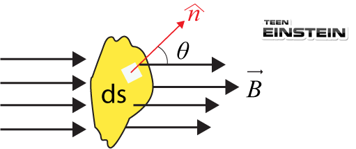
aContents:IntroductionDefinitionMagnetic flux and its dimension and UnitsFaraday’s Law of InductionLenz’s Law6.1 Introduction:In the early decades of nineteenth century, the inter-relation between electricity and magnetism and also the fact that electricity (moving charges) produces magnetism was established by Oerested, Ampere and other renowned scientists. In 1831, Michael Faraday (From England) and Joseph Henry (From U.S.A) had independently and discovered the most surprising reverse effect of electromagnetism, i.e. moving magnet can produce an electric field which produces a current in a close loop of conducting wire.Electromagnetic Induction: The phenomenon in which an induced emf (and hence an induced current) is generated by a time varying magnetic flux linked with a closed circuit, is called electromagnetic induction.6.2 Magnetic flux:The magnetic flux through any surface placed in magnetic field is defined as the number of magnetic field lines crossing the surface normally.● It is measured by the product of the magnetic field along the direction of normal to the surface area.● Numerically magnetic flux is expressed as 𝜙=→
B
.→
A
.=→
B
.(nA)=BAcos𝜃, where n is in the outward normal direction of the area.
Figure-6.1: Magnetic flux for a plane surface.
● If the surface is not a plane surface or not a uniform one, then magnetic flux has to be calculated by estimating magnetic flux through an elemental surfaces area ds and then integrating that for the whole surface area i.e., 𝜙=∫s→
B
.(nds).
Figure-6.2: Magnetic flux through a surface of non-uniform shape
● Dimension of flux: We know, 𝜙=BA.Again, from the magnetic force B=F
qv.● Hence dimension of flux, [𝜙]=[F][A]
[q][v]=[MT-2][L2]
[AT][L-1]=[ML2T-2 A-1].● SI Unit of Flux: Weber (Wb). ● One weber is defined as the flux produced when a uniform magnetic field of one tesla acts normally over an area of 1m2● i.e., 1 Wb=1T m2.● CGS Unit of Flux: Maxwell (Mx)● ai.e., 1 Mx=1G cm2. 1 Wb=108 maxwell.● 6.4 Faraday’s Law of InductionThe magnitude of the induced emf (𝜖) in a conducting loop is equal to the time rate of change of magnetic flux (𝜃B) through that loop. It is mathematically written as 𝜖∝d𝜙B
dt⇒𝜖=-d𝜙B
dt● Here minus sign indicates the direction of the induced emf and this sign was given by German Physicist Henrich Friedrich Lenz. If there are number of turns the law can written as 𝜖=-Nd𝜙B
dt● If the flux changes from 𝜙1 to 𝜙2 in time t then the average induced emf will be given as 𝜖=-N𝜙2-𝜙1
t● The magnitude of the induced emf can be changed by changing the flux (𝜙=→
B
.→
A
). That can be done by (i) changing the field →
B
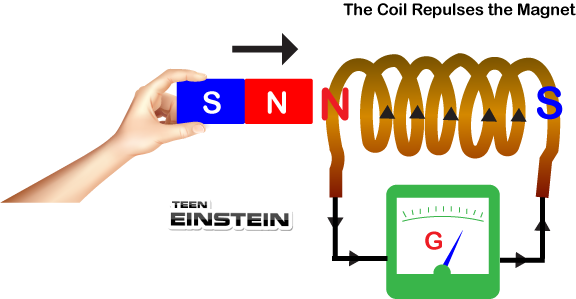
within the coil (ii) changing either the total area of the coil or portion of that within the magnetic field and (iii) changing the angle between the direction of the magnetic field and the outward normal to the plane of the coil.6.5 Lenz’s Law German physicist Henrich Friedrich Lenz proposed a law for determining the direction of induced emf and the induced current in the coil.Lenz’s law states that the polarity of the induced emf will be such that it tends to produce a current which opposes the cause which produces it, i.e., the change in magnetic flux.● When the north pole (N) of a bar magnet is brought towards a closed coil the magnetic flux passes through the coil increases, the induced current flows in the counter-clock-wise direction such that it produces the north pole (N) in front of the coil to repeal the north pole of the bar magnet and thereby reduces the rate of increase in flux. The situation is shown in the figure-6.3.
Figure-6.3: Direction of induced current when the bar magnet is moved towards the coil
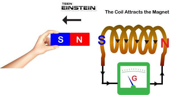
Figure-6.4: Direction of induced current when the bar magnet is moved away from the coil
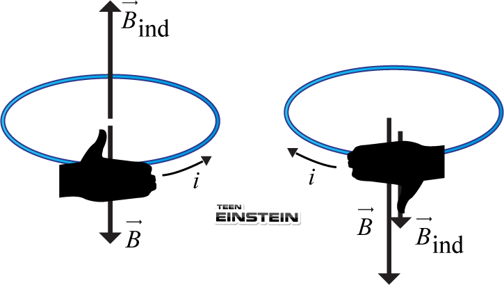
● When the bar magnet is moved away from the coil the flux through the coil decreases, the induced current flows in the clock-wise direction such that it produces south pole (S) in front of the coil to attract (or pull) the north pole of the bar magnet and thereby reduces the rate of decrease in the flux (Figure-6.4).● The direction of the induced current can be obtained using the Fleming’s Right-hand Rule (The rule is demonstrated in the next section).● The easiest way to find the direction of induced current in any loop is to use right-hand thumb rule to find the direction of the induced magnetic field (Bin).● When the linked magnetic flux tends to increases, the current has to be in a direction that produces an induced magnetic field (Bin) in the direction opposite to the direction of the original field (B) (shown in the Figure-6.6.-a)● When the linked magnetic flux tends to decreases, the current has to be in a direction that produces an induced magnetic field (Bin) in the same direction as that of the original field (B) shown in the Figure-6.5(a-b).
Figure-6.5(a-b): Direction of induced current & induced magnetic field (→
B
ind)when original external magnetic field →
(B
)(a) increases and (b) decreases.
6.5.1 Lenz’s Law and Law of Energy Conservation● Lenz’s law is a consequence of conservation of energy.● According to Lenz’s law the induced emf (current) in the coil always opposes the motion of the bar magnet. Therefore work has to be done in order to move the bar magnet towards the coil or away from it. This work done or mechanical energy gets converted into the electrical energy (in the form of induced current).● If Lenz’s law is not valid then the induced current in the coil would attract the north pole of the bar magnet while it approaches towards the coil or repeal the north pole while it moves away from the coil. In this way the velocity of the bar magnet would gradually increase and hence its kinetic energy even without expending an equivalent amount of energy. This is against the law of conservation of energy.
Subscribe
Would you like to receive our Newsletter, NEET- IIT Videos, STEM Materials, NEET-IIT Solved previous year question papers.
Book Your Demo Class
Try for 1 Month @
$20 only few seats available. Offer Ends Soon.
Book now and get your free unlimited TeenEinstein Portal Access.
You are now subscribed to our Newsletter etc.
Would you like to continue Free Trial.
TeenEinstein Stem Platform Portal access for 30 days Would you like to get the Portal access free trial for 30 days .